DORIS mission on
SPOT 4
DORIS after SPOT 4
The DORIS system (Doppler Orbitography and Radiopositioning
Integrated by Satellite) was designed and developed by CNES, the Groupe de Recherches de
Géodésie Spatiale, GRGS (CNES/CNRS/Université Paul Sabatier) and the Institut
Géographique National (IGN) to meet new needs for the precise location of satellites on
their orbits and of terrestrial beacons.
DORIS is an RF system using a dual-frequency Doppler (400 MHz and 2 GH2) uplink to measure the velocity of a satellite in orbit relative to a global, permanent network of fifty-one so-called "orbitography " beacons. At the same time the system can be used to locate beacons on the ground. Two "master " beacons serve as time and frequency references for the system and also handle uploading of the commands and data needed by the onboard receiver.
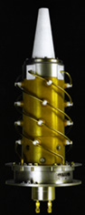
Antenna (STAREC)
The DORIS passenger consists of a receiver (MVR- range rate measuring device), a USO ( ultrastable oscillator) and an omnidirectional antenna all carried on the host satellite. The receiver takes Doppler shift measurements of 400 MHz and 2 Ghz radio signals transmitted by the beacons. The 400 MHz measurement is very useful for correcting errors caused by ionospheric propagation.

MVR (Dassault Électronique)
Measurement data for permanent network beacons are processed to yield the satellite's precise trajectory. This processing includes modelling of forces acting on the satellite ( terrestrial gravitation, etc.) in order to determine its precise trajectory. The resulting orbit calculation is then used to determine the precise location of the beacons and their changing positions.
The main missions of DORIS/SPOT 4 are:
| position determination to within better than | for one satellite | using several satellites |
| on one pass | 1 m | 50 cm |
| in one day | 20 cm | 15 cm |
| in five days | 10 cm | 7 cm |
| in twenty-six days | 3 cm | 1.1 cm |
Using as input a calculation of the absolute
velocities of all the DORIS beacons, it is possible to deduce the relative
movements of tectonic plates ; for instance, the distance between Europe and
North America, which is increasing by 2 cm per year. Thanks to its global coverage, the
DORIS system is now able to measure all of these shifts precisely.
A first time record for DORIS : using the DIODE navigator, DORIS
determines the satellite's orbit in real time, with an accuracy of 3 m along the three
axes (x, y, z).
Current development should lead in 1999 to a miniaturized DORIS receiver useable as a micro-satellite payload. DORIS will then be a competitive satellite navigation system.
The DIODE navigator is being tried out on SPOT 4. Once validated it will be integrated in the DORIS instrument and delivered "as standard equipment" for ENVISAT, JASON-1, SPOT 5, etc.
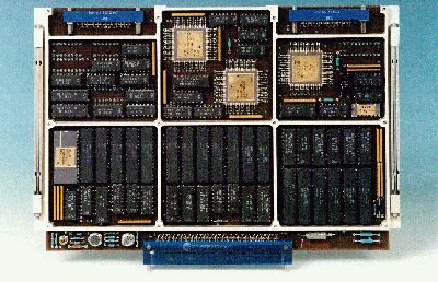
![]()
DIODE means "Détermination Immédiate d'Orbite par Doris Embarqué" or immediate onboard orbit determination by DORIS. It is part of the DORIS instrument, which calculates the satellite's position and velocity.
This type of equipment calculates the position of the host satellite, a little like a captain on the high seas, who determines his ship's position (with a sextant, or, in the case of DORIS, in relation to beacons) : this is referred to as "satellite navigation". This is why DIODE is often called the " Navigator ".
When a ground station receives the scenes taken by the satellite, their precise
locations have to be determined. Moreover, they have to be corrected to ensure maximum
quality. To do this, we need to know where the satellite was when the scene was acquired
(in order to account for the Earth's curvature and rotation, for example).
DIODE's role is to calculate the satellite's position in real time, on board the
satellite. It is then possible to automatically "tag " the scenes at the time
they are acquired.
The satellite acquires a scene and DIODE gives the satellite's position at that instant.
The imagery and position information are available together, with no further processing, when they are received by the ground station.
The geographical location of SPOT 4 scenes must be known to within approximately 100 metres : DIODE, using the precise measurements provided by DORIS, determines SPOT 4's position to within a few metres.
Traditionally the positions of Earth observation satellites were predetermined by the Operations Control Centre (according to the previous day's trajectory and using satellite orbit determination programmes). These were periodically sent to the Direct Receiving Stations.
The DIODE procedure is thus:
The " passenger " instruments can use this information as well : POAM and the Vegetation payload will also use the Navigator data for their own needs.
Almost! A few commands have to be sent to adjust the Navigator's operation, but only a very small amount of data has to be sent to it on a routine basis. During the six month validation phase on the ground only five commands had to be sent.
The first DIODE instrument requires a (very approximate) starting position for the satellite. Later versions will not need this as they will be programmed with an autonomous initialization function.
 CNES
started the project in 1991 : the electronics board was made by Dassault Electronique
(which had already supplied the DORIS receiver). Dassault also developed the Navigator's
real-time programme.
CNES
started the project in 1991 : the electronics board was made by Dassault Electronique
(which had already supplied the DORIS receiver). Dassault also developed the Navigator's
real-time programme.
The orbit determination software (which calculates the satellite's position) was developed by CNES with technical support from COFRAMI. It has 2 500 lines of code (HOOD method for the design and Ada language for the encoding), requiring 60 Kbits of memory.
Every 10 seconds, the programme carries out the following operations:
DIODE has never been carried on a satellite before SPOT 4 : the other DORIS instruments, flown on SPOT 2, SPOT 3 and TOPEX-POSEIDON are not fitted with the Navigator. Their measurements were collected by the ground segment and used to develop the DIODE instrument.
In this way it was " fed " on all of the measurements produced by the DORIS instrument on SPOT 3. DIODE received input of SPOT 3 orbit data throughout its lifetime, just as if it had been on board the satellite. Since November 1997, DIODE has continued operating with SPOT 2 measurements, and has therefore been in service for several years now, but on the ground.
Several series of tests were carried out on the SPOT 4 satellite (on the ground, during cleanroom checks) to ensure that the Navigator was operating satisfactorily.
It now has to be proven that DIODE operates correctly in orbit and that it provides a reliable service.
DIODE is already an integral part of the new DORIS receivers to be carried on the European observation satellite, ENVISAT, on SPOT 5 and on JASON (an altimetry satellite). These DORIS receivers have been extensively redesigned and improved. DIODE has also been changed and is now more accurate, since it will be capable of real-time onboard position determination to within one metre.
All users of the DORIS system will now have access to onboard orbit determination services, which undoubtedly offer many advantages over previous systems. Several other space agencies have developed similar systems. In the years to come, satellites will be automatically controlled ( in particular with the advent of large satellite constellations) and it is likely that completely autonomous orbit control systems will soon be developed. CNES, with DIODE/DORIS/SPOT 4, among others, is playing an active role in this.
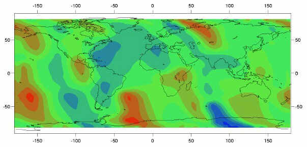
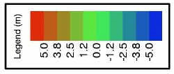
This figure shows, for 6 December 1997, the difference in metres between the altitude of the SPOT 2 satellite, calculated in real time by DIODE, and a reference calculation (done off-line using the precise orbit determination software, ZOOM).
![]()
page updated on the 00-06-06