|
|
|
|
|
![]()
The SPOT Earth observation system designed by CNES and operated by its subsidiary, Spot
Image, has been in operation since February 1986. In March 1998 the SPOT
4 satellite added its new capabilites to the SPOT family thus enabling Spot Image to
satisfy the requirements of users who are now familiar with space imagery.
To ensure continuity of service, SPOT 4 will have the same geometric imaging
characteristics (a swath of 60 km per instrument and oblique viewing capability of 27° on
each side of the local vertical).
However its performance has been increased by adding a new shortwave infrared spectral
band (SWIR), extending its nominal lifetime from 3 to 5 years and improving operational
possibilities.
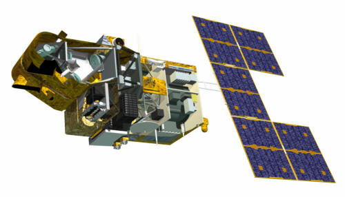 The general architecture of the satellite may be divided into two main
parts :
The general architecture of the satellite may be divided into two main
parts :
![]()
The platform provides the following functions :
The propulsion module consists of a frame made of aluminium bars and two capillary tanks holding 158 kg of hydrazine. These supply the thrusters which are used to control the satellite's attitude and orbit.
The service module is basically the same, but its equipment, structure and flight software have been upgraded. The module itself is built around a central thrust tube, which is the satellite's backbone. The service module houses the battery compartment.
The electrical design and computer systems are unchanged. However the service capabilities of the platform have been extended by upgrading most of the electrical subsystems (solar array, energy storage, performance of the onboard data handling subsystem, increased size of the attitude control subsystem).
![]()
The payload carries out the main mission. This consists of a payload equipment bay (PEB) and two HRVIR imaging instruments and Vegetation. The 'passengers' are for the most part mounted on the payload.
The PEB is made of a carbon fibre composite, which ensures dimensional stability for the instruments. The bay houses the electronics for image processing, recording and telemetry (downlinking to the ground segment).
These image data are compressed and formatted and then stored on the satellite, either by magnetic tape recorders holding about 40 minutes of imaging time, or in a solid-state memory (such as in computers) holding about 3 minutes of imaging time. The image data are either sent directly to Earth, if a receiving station is within range of the satellite, or later, after storage as described above, when the satellite passes over one of the two main stations at Toulouse or Kiruna. The transmission channel operates at 50 Megabits per second (which may be compared with Internet rates of the order of a few kilobytes per second).
On SPOT 4, the data may also be transmitted by an optical link with a geostationary, European Space Agency satellite, Artemis. This new transmission channel uses the PASTEL instrument payload.
The two HRVIRs for High Resolution Visible and Infrared, are derived from the SPOT 1/2/3 design. The opto-mechanical architecture has again been used (incorporating a telescope, a calibration system and other devices). The main innovation is the addition of a channel in the shortwave infrared spectrum (SWIR - 1.5 to 1.75 mm).
This new spectral band required the design of a special detection unit (detectors, etc.), a lower operating temperature and temperature control to within a hundredth of a degree.
 Concerning
the mechanism itself, a steerable strip-selection mirror for changing the viewing axis increases the
satellite's operational performance. It enables repeated observations of the same area at
short intervals and acquiring an image of the same scene from different perspectives (to
provide stereopairs). Moreover its ability to cover a scene, the basic ground area to be
observed, is increased due to the fact that the two instruments generally operate
independently. For instance, one instrument acquires an image with the greatest possible
viewing angle to the left of the ground track while the other sets its mirror to obtain an
image to the right of the ground track.
Concerning
the mechanism itself, a steerable strip-selection mirror for changing the viewing axis increases the
satellite's operational performance. It enables repeated observations of the same area at
short intervals and acquiring an image of the same scene from different perspectives (to
provide stereopairs). Moreover its ability to cover a scene, the basic ground area to be
observed, is increased due to the fact that the two instruments generally operate
independently. For instance, one instrument acquires an image with the greatest possible
viewing angle to the left of the ground track while the other sets its mirror to obtain an
image to the right of the ground track.
![]()
page updated on the 00-06-06