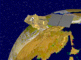
Local orbital
reference system
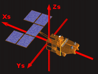
Bus modes
Unlike an aircraft which uses its attitude to control its trajectory (pitching to go
up, banking to turn, etc.) the angular motion of a satellite, which is travelling in a
vacuum, has practically no effect on its trajectory (i.e. its orbit).
The satellite's orbit is determined by the initial velocity
given to it by the Ariane launcher, and then by the small corrections made regularly by
micro-thrusters.
Attitude control (angular orientation) is needed so that the optical system covers the
programmed ground area at all times. However, the satellite tends to change its
orientation due to torque produced by the environment (drag of the residual atmosphere on
the solar array, solar radiation pressure, etc.) or by itself (due to movement of
mechanical parts, etc.). Thus the angular orientation has to be actively controlled.
Another reason is the need to prevent "blurring " of the scenes acquired.
The attitude is continuously controlled by a programmed control loop: sensors measure the satellite's attitude, the onboard computer then
processes these measurements and generates commands which are carried out by the actuator, to ensure correct pointing.
SPOT 4 is "three-axis stabilized", which means that its orientation is
fully controlled relative to three axes. One of these directions corresponds to the line
between the satellite and the centre of the Earth, also called the "geocentric
direction " another is perpendicular to this geocentric axis, in the direction of the
satellite's velocity vector; the third is perpendicular to the first two. These three form
the local orbital reference system.
 The
local orbital reference system is
defined at each point of the orbit by three unit vectors. These vectors are derived from
the satellite position and velocity vectors:
The
local orbital reference system is
defined at each point of the orbit by three unit vectors. These vectors are derived from
the satellite position and velocity vectors:
- Vector L is colinear with position vector P (on the axis between the Earth's centre and
the satellite). It defines the yaw axis.
- Vector T is perpendicular to the orbital plane (vector L, vector V). It defines the
pitch axis.
- Vector R completes the set of orthogonal axes. it lies in the plane defined by Vectors L
and V and defines the roll axis. It does not coincide exactly with the velocity vector due
to the eccentricity of the orbit.
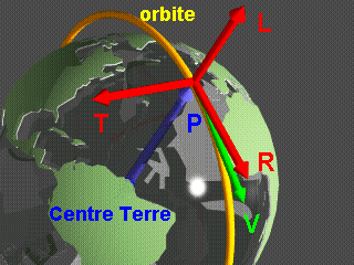
 satellite axes
Axes Xs, Ys, Zs represent an orthogonal reference frame related to the satellite (satellite
axes). Nominal attitude pointing consists of the best possible alignment of this
set of axes with the local orbital reference system
(while ensuring stability and limiting angular rates about this position).
With perfect geocentric pointing, this gives:
Xs = -T
Ys = -R
Zs = L
top of page, article
The following equipment is used for attitude control:
sensors :
- an inertial platform consisting of four rate gyros ; these are two-axis
rate gyros and two of them are enough to provide angular rate measurements along the three
axes of the satellite. The two others are thus used as back-ups,
 - two digital
Earth sensors (STD), one nominal and one redundant, are used to measure
angular displacement about the pitch and roll axes,
- two digital
Earth sensors (STD), one nominal and one redundant, are used to measure
angular displacement about the pitch and roll axes,
- two digital Sun sensors (SSD), one nominal and one redundant, are used
to measure angular displacement around the yaw axis (once per orbit).
actuators :
- Three magnetic-bearing reaction wheels (RRPM) ae used to apply torque
to the satellite and thus to rotate it about one of the X, Y or Z axes.
- Two magnetic torquers (MAC), which, through interaction with the
Earth's magnetic field, create torques which are used to control the speed of the reaction
wheels.
 - Two
types of thrusters (burning hydrazine) each producing a force of 3.5 or
15 Newtons; their orientation relative to the satellite's centre of gravity inducing
rotation about one of the axes, X, Y or Z.
- Two
types of thrusters (burning hydrazine) each producing a force of 3.5 or
15 Newtons; their orientation relative to the satellite's centre of gravity inducing
rotation about one of the axes, X, Y or Z.
In addition, an AOCS (Attitude and orbit control system) is linked to the solar array
drive mechanism. It ensures that the array tracks the Sun as the satellite moves along its
orbit. The sunlight collected by the solar array during the illuminated part of the orbit
is converted into electrical power for the satellite and for charging batteries which are
used during the eclipse part of the orbit.
top of page, article, section

Each bus mode corresponds to a specific configuration of an item of equipment and the
execution of certain flight software procedures.
For SPOT 4, these modes and the transitions from one to another can be described as
follows:
MLT :
Launch mode
- Initial configuration of flight equipment and software. This mode is only used during
the launch phase. The rate gyros in particular are only powered-up when the satellite
separates from the launcher and the reaction wheels are kept caged. (return to mode diagram)
MRV:
Rate reduction mode
- This mode is first used to reduce angular rates (by activating thrusters) about each
satellite axis following separation from the launcher and first deployment of the solar
array. It can be used again in the event of an anomaly during the satellite's lifetime;
switching-over is controlled either by the flight software or by the control centre. Once
the angular rates have been sufficiently reduced, the MAG mode is automatically activated.
(return to mode diagram)
MAG:
Coarse acquisition mode
- This mode is used to align the satellite with the geocentric direction using information
from the Earth sensor, STD, and the rate gyros and by activating thrusters. Following this
acquisition, the pointing accuracy about the pitch and roll axes is around 5 degrees. When
this accuracy has been achieved, the MAF1 mode is automatically activated. (return to mode diagram)
MAF1:
Fine acquisition mode "1"
- This mode is used to point the satellite around the yaw axis. It is done by activating
thrusters and mainly uses input from the rate gyros. When the yaw pointing direction has
been achieved the MAF2 mode is automatically activated. (return to mode diagram)
MAF2:
Fine acquisition mode "2"
- MAF2 is a stable mode which keeps the satellite oriented on its three axes by means of
thrusters. (return to mode diagram)
MDG:
Solar array deployment mode
- This mode is used while the solar array is being deployed. The perturbations caused by
this movement then make it necessary to repeat the slowing down and pointing acquisition
sequence (MRV -> MAG -> MAF1 -> MAF2). Following this operation (if it has been
carried out correctly), the solar array starts tracking and the reaction wheels are
released. (return to mode diagram)
|
Illustration
showing deployment of the solar arrays :
Primary deployment on the left. (277 kbyte)
Secondary deployment on the right (387
kbyte) |
|
MPF:
Fine-pointing mode
- This is the nominal satellite pointing mode; it ensures the necessary stability and
precision pointing for image acquisition. The attitude is controlled by the reaction
wheels and magnetic torquers (attitude is more accurate than when using thrusters); this
is based on data from rate gyros which are recalibrated using STD and SSD sensor
measurements. This pointing is accurate to within 0.15 degrees around each axis with
angular rate stability of 8. 10-4 degrees per second.
Once the satellite has achieved the MAF2 mode, only the ground segment can switch it to
the MPF mode. This mode completes attitude acquisition; the satellite is then operational
for carrying out its mission. (return to
mode diagram)
MCC:
Small- amplitude orbit control mode
- This mode is used to correct the satellite's trajectory in its orbital plane; the
amplitudes of these corrections are sufficiently small that attitude can be controlled by
means of reaction wheels. Certain thrusters are combined to produce a resultant force
vector (and not just a torque) which can increase or reduce the satellite's velocity. The
thruster propulsion needed for this mode is calculated by the orbit control centre and
uploaded to the flight software which then activates the thrusters. The frequency of this
type of manoeuvre depends on the solar activity (at intervals of from 2 weeks to 2
months). (return to mode diagram)
MCO:
Large- amplitude orbit control mode
- This mode is used to correct the satellite's trajectory in or out of the orbital plane,
the corrective manoeuvres have a large amplitude. Attitude control is maintained by
thrusters by combining programmed thrust manoeuvers and attitude correction manoeuvres.
For thrusting manoeuvres out of the orbital plane (mainly in order to correct the orbit
inclination), the satellite first rotates around the yaw axis to orient the thrusters in
the required direction The thruster impulses needed for this mode are calculated by the
orbit control centre and uploaded to the flight software which then activates the
thrusters. This type of manoeuvre is performed about once every 6 months. (return to mode diagram)
MSU: Safe
mode
- In the event of a serious anomaly which cannot be automatically processed and corrected
on board, the satellite can be put into safe mode either by the flight software or by
hardware failure override. This mode is used to ensure the satellite's vital functions
(onboard power, thermal regulation), while the failure is being analysed (ground
communications functions). For this purpose, the satellite is controlled by autonomous
flight software, dedicated for the safe mode. The attitude is controlled by means of
thrusters to keep the +Z side pointed towards the Sun, with the solar array in a set
position. This pointing mode uses measurements from two solar acquisition sensors (SAS)
dedicated for the safe mode.
Following a command from the ground segment, the satellite returns to the nominal mode by
means of a MRV -> MAG -> MAF1 -> MAF2 sequence. (return to mode diagram)
top of page, article, section
page updated on the 00-06-06