Architecture of the HRVIR instrument
Telescope
Detection unit
Image processing electronics
Oblique viewing capability
System and calibration principles
| Principle
and optical path Architecture of the HRVIR instrument Telescope Detection unit Image processing electronics Oblique viewing capability System and calibration principles |
|
 The
HRVIR imaging instrument is designed to acquire, instantaneously, one complete line of
pixels at a time covering the entire field of view. This is achieved using charged-couple
device (CCD) linear array.
The
HRVIR imaging instrument is designed to acquire, instantaneously, one complete line of
pixels at a time covering the entire field of view. This is achieved using charged-couple
device (CCD) linear array.
Special optical devices forming a so-called "spectral separator" separate the in-coming light (from target area on the ground) into four spectral channels.
The CCD linear arrays operate in the so-called "push-broom" mode. A wide-angle telescope forms an instantaneous image of adjacent "ground patch areas" on a row of detectors in the instrument's focal plane.
Column-wise scanning is a direct result of the satellite's motion along its orbit. The
signals generated by the detectors (photodiodes) are read out sequentially at a
predetermined clock rate. Thus, although the linear arrays do not "scan" in the
line-wise direction to gather light, the detectors are scanned electronically to generate
the output signal.
The telescope has a field of view of 4°, corresponding to 60 km on the ground covered instantaneously by a line of 6000 detectors. Each HRVIR is thus said to offer a "strip width" of 60 km.
As just mentioned, each detector generates one pixel at a time, each pixel corresponding to a ground patch area measuring 10 metres square in the high-resolution mode. When adjacent detectors are electronically scanned in pairs, they yield pixels corresponding to a ground patch area measuring 20 metres square resulting in imagery with 20-m resolution. The satellite's motion along its orbit results in successive scanlines, hence complete images.
The HRVIR instrument has two operating modes, depending on whether the detectors are read out singly or in pairs. The image quality is very high, partly because no moving parts are involved in image generation.
The light entering the HRVIR is sunlight reflected by the Earth's surface then gathered by a telescope with a focal length of 1.08 m and an aperture of ƒ/3.5. The in-coming beam is split into four spectral channels by a beam-splitter consisting of prisms and filters, then focused onto four rows of detectors. As just mentioned, four rows of detectors simultaneously generate four lines of "registered" pixels; in other words a single line of landscape is simultaneously observed in four perfectly registered spectral bands.
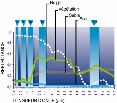
SPOT 4 uses four spectral bands as follows:
|
|
These bands were chosen:
The instrument has three viewing modes:
![]()
The main components of the HRVIR instrument are:
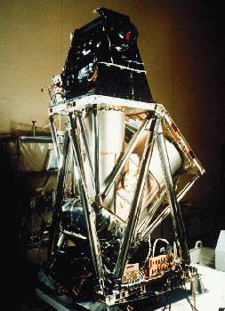 Telescope
 The optical combination forming the HRVIR telescope is based on the catadioptric Schmidt telescope. It features a concave mirror which converts the incoming parallel beam into a beam converging on the focal plane:
This rear doublet can be accurately adjusted relative to the telescope's main axis to provide focus adjustment for all focal planes. This capability is used on the ground and can also be used in orbit to correct any movement of optical components due to launch vibration or the orbital out-gassing of carbon-fibre components.
The detection unit, mounted in the telescope's focal plane, uses a combination of dispersive components (i.e. beam-splitting filters and prisms) to separate the four spectral channels then to acquire and convert the incoming light into electrical signals.
CCD (charge-coupled device) linear arrays are used as sensors, there being one sensor assembly in the focal plane of each of the four spectral channels. To acquire a 60-km-wide strip at 10-m resolution requires 6000 individual CCD detectors. Each complete row of detectors comprises four linear arrays of 1500 detectors each, aligned by a Divoli optical line-butting assembly.
The detectors are read electronically. To obtain an image signal with 20-m resolution, they are read, or scanned, two at a time. The visible channels use silicon CCD arrays similar to those found in video cameras, photocopiers and the like.
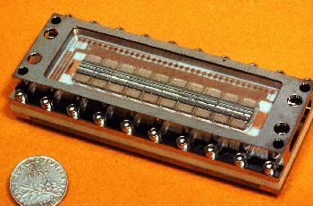
SWIR detector array
The SWIR band (1.58–1.75 µm) uses new-generation InGaAs/InP linear arrays
developed specifically for the purpose. This technology offers high sensitivity in the
SWIR band and good response at room temperatures (an important advantage during laboratory
development). The 3000 detectors required to achieve a ground resolution of 20 m are
aligned in a plane by assembling ten "bricks" end to end, each brick comprising
300 CCD detectors.
The electrical signals produced by the CCD linear arrays are read out via shift
registers then forwarded, at the image-generation clock rate, to the image processing
electronics. The electronics amplifies the signal, adjusts the gain to match the
landscape's dynamic range, then digitizes and formats the signals.
The video module controls the detection unit and processes the video signals it produces.
From here the signals go to data compression and telemetry formatting, then to the data
storage devices or the telemetry transmitter downlinking the image data to ground
receiving stations.
 The
entrance to each HRVIR features a strip-selection mirror enabling the viewing direction to
be adjusted through ± 27° about the nadir. Adjustment is controlled by a stepper
motor moving through increments of 0.3°. For each position, the viewing direction is
accurate to within 200 m on the ground.
The
entrance to each HRVIR features a strip-selection mirror enabling the viewing direction to
be adjusted through ± 27° about the nadir. Adjustment is controlled by a stepper
motor moving through increments of 0.3°. For each position, the viewing direction is
accurate to within 200 m on the ground.
This capability is used in three ways:
 |
|
The illustration shows the swath width covered with the
maximum displacement of the mirrors. The solar panels turn so that they are always pointing towards the sun. |
![]()
The HRVIR instruments also feature a calibration system allowing image signals to be corrected in two ways:
The calibration system is used at regular intervals to check and, if necessary, adjust the instrument response. Some of the effects that may need to be compensated include changes in the transmissivity of optical components as a result of orbital ageing, mechanical distortion due to temperature variations, variations in the noise generated by the image electronics or CCD detectors.
![]()
page updated on the 00-06-06