Engineering model,
Flight model.
Structural and
thermal mockup,
Engineering model,
Flight model.
The initial programme phases (known as phases A and B or preliminary analysis and system definition) result in the definition of the design concepts for the spacecraft, its onboard equipment and subsystems. The next phase (phase C or detailed design) focuses on the detailed design of onboard equipment and subsystems. The final phase ( . . . you guessed it . . . phase D, also termed validation or development) aims to validate the concepts and designs by building various models and mockups, then by assembling (or integrating) the flight model.
For the Spot programme, the main steps of the validation phase are:
Both a mockup and a model . . . that may sound a little extravagant. But remember, the loss of a flight model simply because it couldn't withstand some load or stress is unacceptable. And would, in any case, be many time more expensive . . . especially if it occurred while the satellite is not in contact with a ground station, leaving it hurtling through space, helpless.
The structural and thermal mockup undergoes two main types of design validation test:
This model is assembled using items of equipment qualified specifically for integration models. Generally speaking, these items are fully functional. They are, however, made of more common grades of components (i.e. not from space-qualified components). Nor are these items required to withstand the mechanical and thermal stresses applied to the mechanical and thermal mockup.
 Engineering
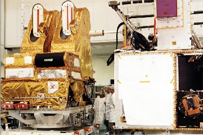
model EM is used to validate the spacecraft's electrical and functional design. Like the
flight model, it comprises two main parts, namely the satellite bus and the satellite payload.
Engineering
model EM is used to validate the spacecraft's electrical and functional design. Like the
flight model, it comprises two main parts, namely the satellite bus and the satellite payload.
Although the EM model will never fly, its integration and testing are important both in
themselves and as training exercises for the teams involved. The main phases are:
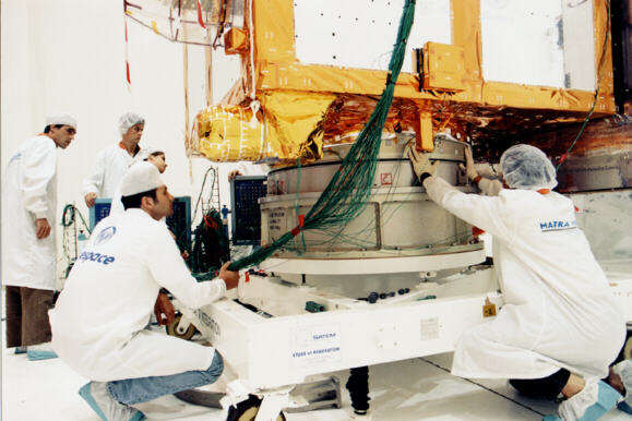
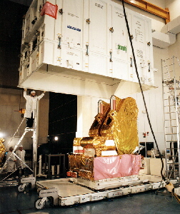
The mechanical and thermal design having been validated using the STM mockup, the electrical design, operation and procedures having been validated using the EM model, and the equipment for the flight model having successfully passed acceptance testing (and formally declared ready for service), work can begin on the integration of the flight model. So far as possible, the assembly and test sequences applicable to the bus and its payload are conducted in parallel.
The long succession of assembly and test sequences includes such tasks as:
Before and after each major test, the satellite, payload or bus undergoes a series of reference tests to ensure that the model's mechanical, electrical and thermal properties remain unchanged. Similarly, each time the payload and bus are mated, the assembly undergoes a general health check.
 |
 |
 |
The last steps involve final preparations for shipping and the packing of the payload, bus and solar array into separate containers.
![]()
page updated on the 00-06-06
